![]()

Last update January 29th 2020
GS35B HIGH POWER LINEAR AMPLIFIER
FOR VHF/2M/144MHz
DESIGN and HOMEBREW by F1CXX
I realized in
1976 a 144 MHZ amplifier with a 4CX1500b. Power outpout is 1100 watts.
At the time, I was inspired by the realization of our friend Daniel F1DRR (SK) with
some modifications.
To date this amp is still in Contests operation.
In 2003, I
decided to build another amplifier with a triode GS35b for the 144 mhz.
These tubes are robust and still reasonably priced.
This realization comes from documents retrieved on the internet (RX1AS, OK1BAF, SM5BSZ, F5MSL, etc ...) and also a bit of me !!
Before starting construction, I invite you to read the F5MSL recommendations. (1 2 3).
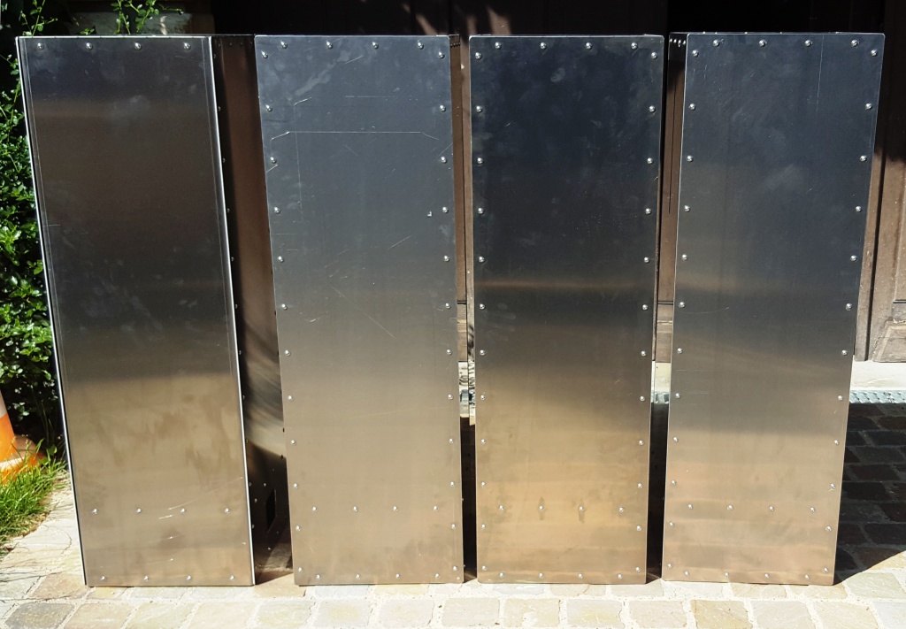
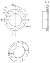
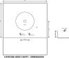
The construction of the ½ wave cavity
Schema
of the cavity
The cavity is
made of aluminum sheet 30 / 10. 20/10 could also be suitable.
The thickness depends of the solidity and the purchase price of the sheets!
The fixing of the plates must include a good number of fixing screws (every 5 cm
on my cavity) in order to obtain a good continuity of mass.
Thoroughly degrease and clean the components before assembly.
I advise you not to use metal sheets because these will cause you in the end of the losses not inconsiderable.
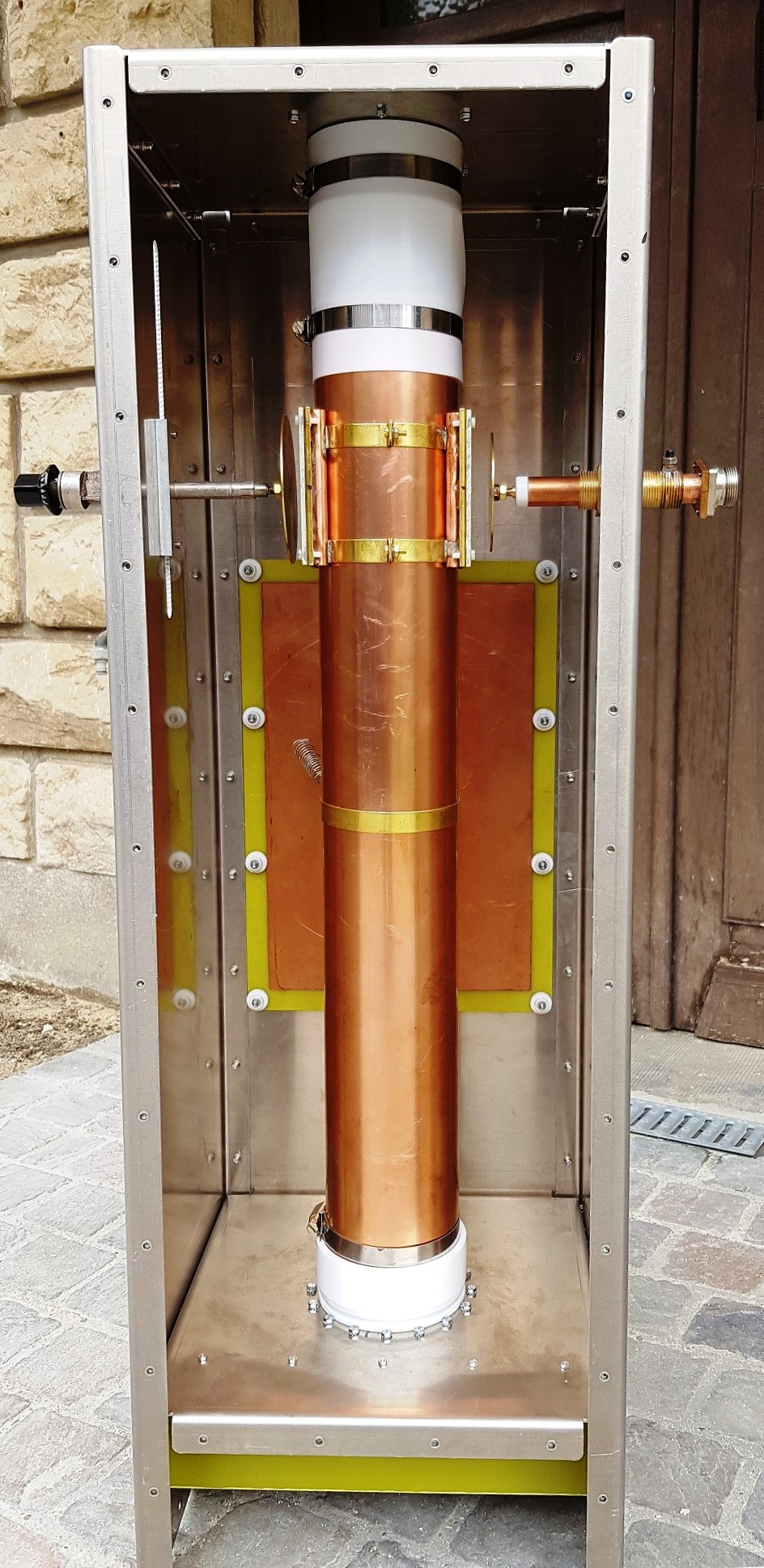
The internal dimensions of the cavity are 308 x 308 mm. The anode line can be made from a sheet of rolled copper.
I opted for the purchase of a tube of descent of copper gutter of diameter 100.

The tip of this tube fits perfectly into the anode of the gs35b. Two slots made
with a metal saw will tighten the tube with a "Serflex" collar.
The choice of the dimensions of the cavity and the tube of 100 gives an ideal
impedance of 72
Ω.
This anode tube will also serve as a chimney for evacuating hot air.
The height of the line is 650 mm from the bottom of the fins of the tube.
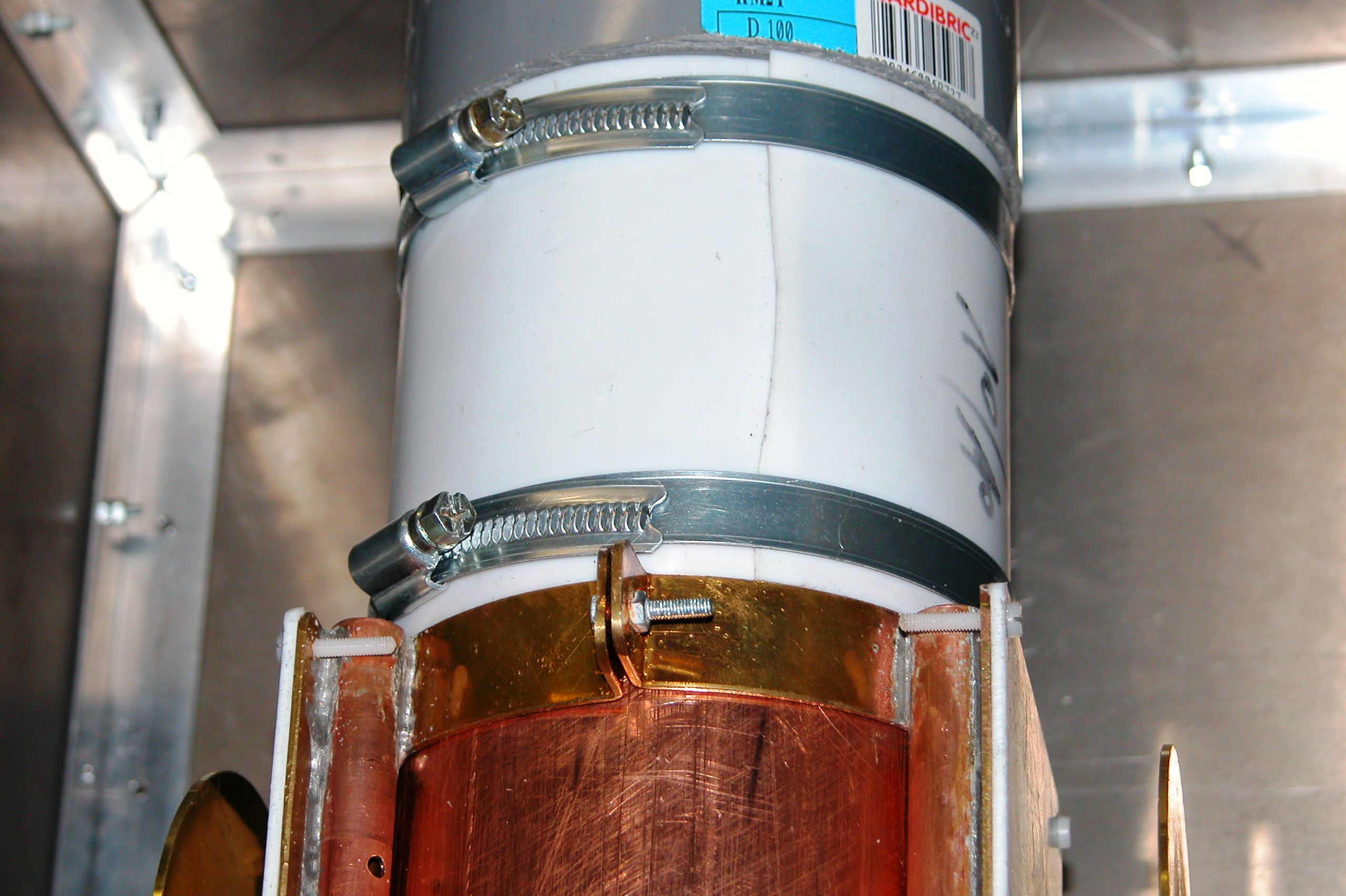
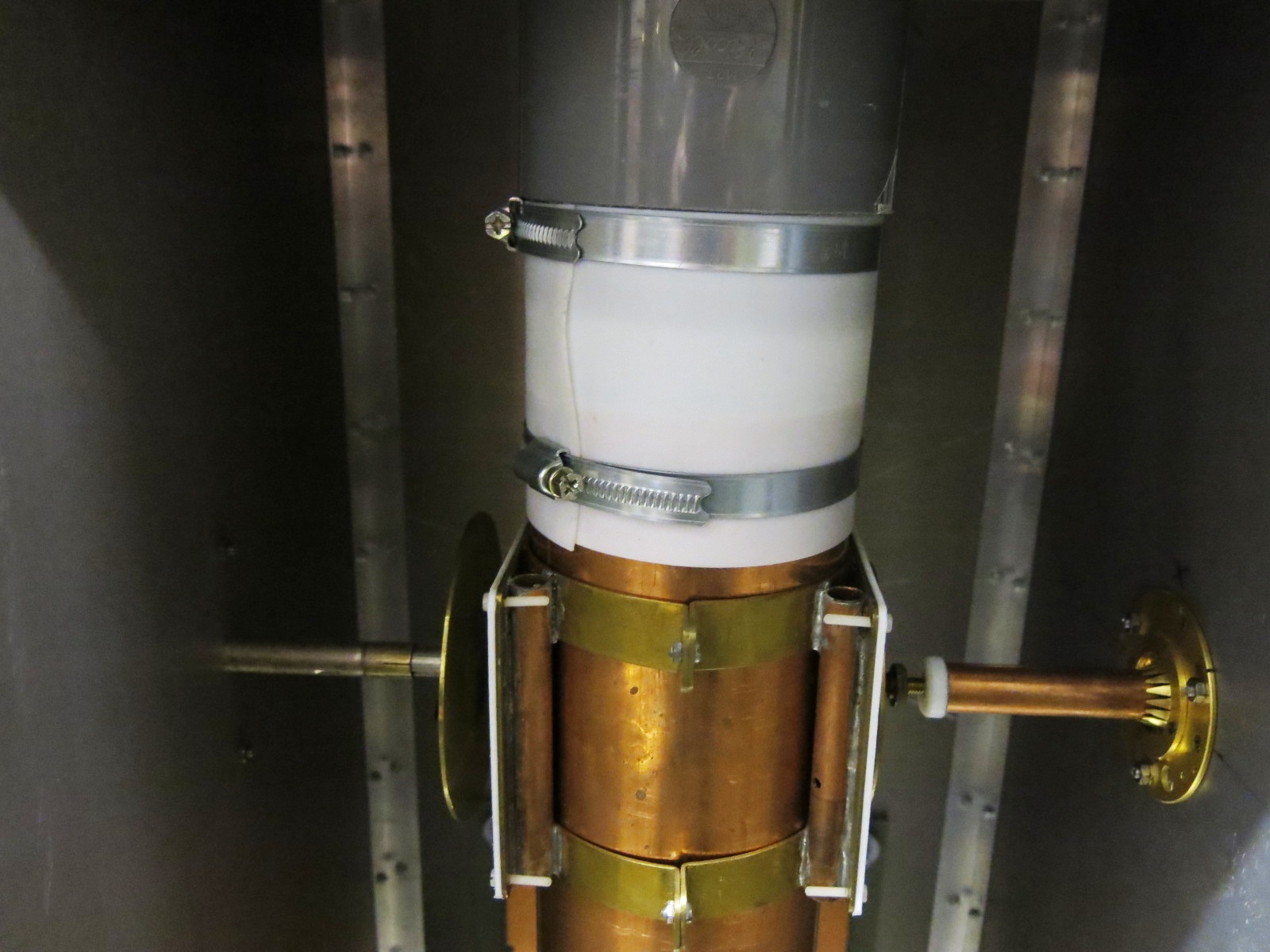
The PVC tube is closed by a fan fan grill. This pvc tube can be replaced by
another system of your choice style metal vent collar attached directly to the
upper and inner part of the Teflon sheet.
The top and the bottom of the Teflon sheet will be fixed by two clamps of the
Serflex type so as to obtain a perfect rigidity of the entire line.
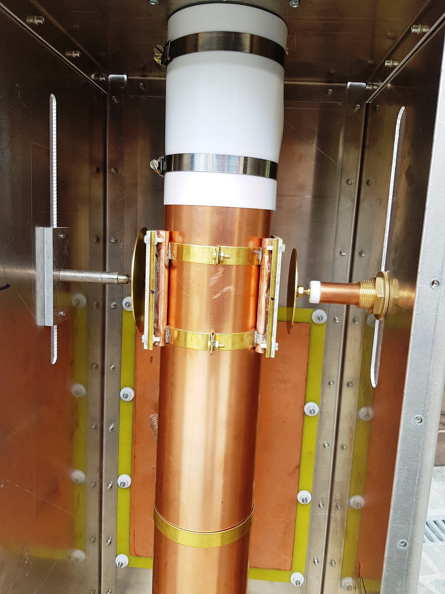
For the plate (TUNE) , I use a "surplus" micrometric recovery screw.
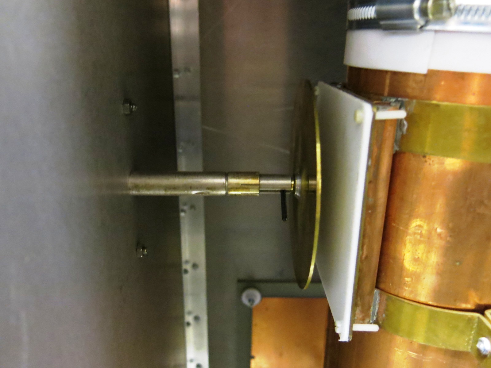
Any other system can be retained provided it has good mass continuity.
For example, the threaded rod alone through a nut should be avoided.
At the end of the micrometric screw is a brass disc of 100mm diameter and a
thickness of about 10/10 to 15/10 depending on your availability.
On the anode
tube is fixed a plate of brass of 100 X 100 surmounted by an epoxy plate or
Teflon of approximately 15/10-
This one is used to prevent that the brass disc comes to make contact on copper
tube or high voltage is present !!
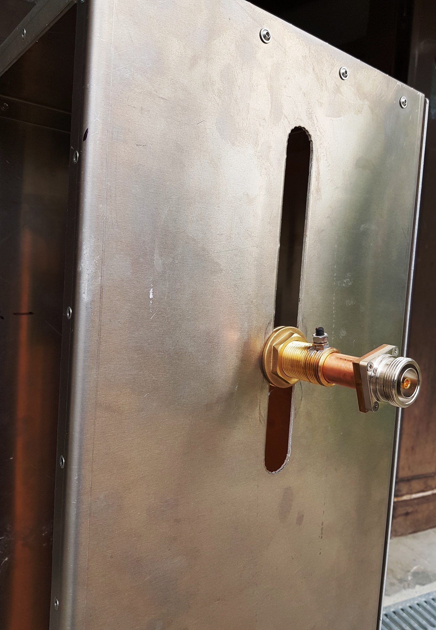
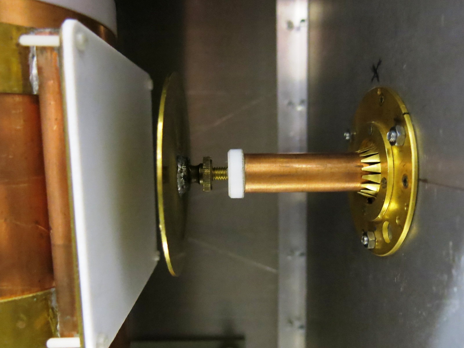
For the antenna tuning (LOAD), I use a pipe of
plumbing copper 14/16 of diameter and inside a threaded shaft of diameter 6mm;
Which gives with APPCAD 50.8 Ω. The assembly slides in a guide made in a piece
of brass.
The rod is fixed at one end to a brass disc of 80 mm and on the other to a DIN
7-16 socket for the antenna output.
The N plugs, with maximum power of the amp do not support the power and are
therefore to be proscribed.
The 14/16 copper tube is welded to the base.


On the anode
tube is fixed a 100 x 100 brass plate topped by an epoxy or teflon plate of
about 15/10.
Prepare a locking screw of about 4 to 6 mm diameter, Output agreement.
The use of a screw is preferable to a Serflex collar because you have only two
hands and it will be difficult at the same time to adjust Pa
and tighten a Serflex collar that will tend to turn when tightening! It is the
experience that speaks !!
NOTE / It is
difficult, depending on the commonly used commercial materials, to respect an
impedance of 50 Ω.
It will be necessary to choose the best choice of tubes and rods in order to get
as close as possible.
(See APPCAD freeware for calculating diameters and impedance). A few ohms
difference is not critical.

Note / the value
of the capacitor depends on the thickness of the substrate used.
(See the freeware RFSIM99 or other for the calculation of the value of the capa).
This substrate will be directly fixed on the wall of the cavity taking care not
to isolate the fixing screws ... attention to the flashes!
The point of attack is located 325 mm from the chassis.
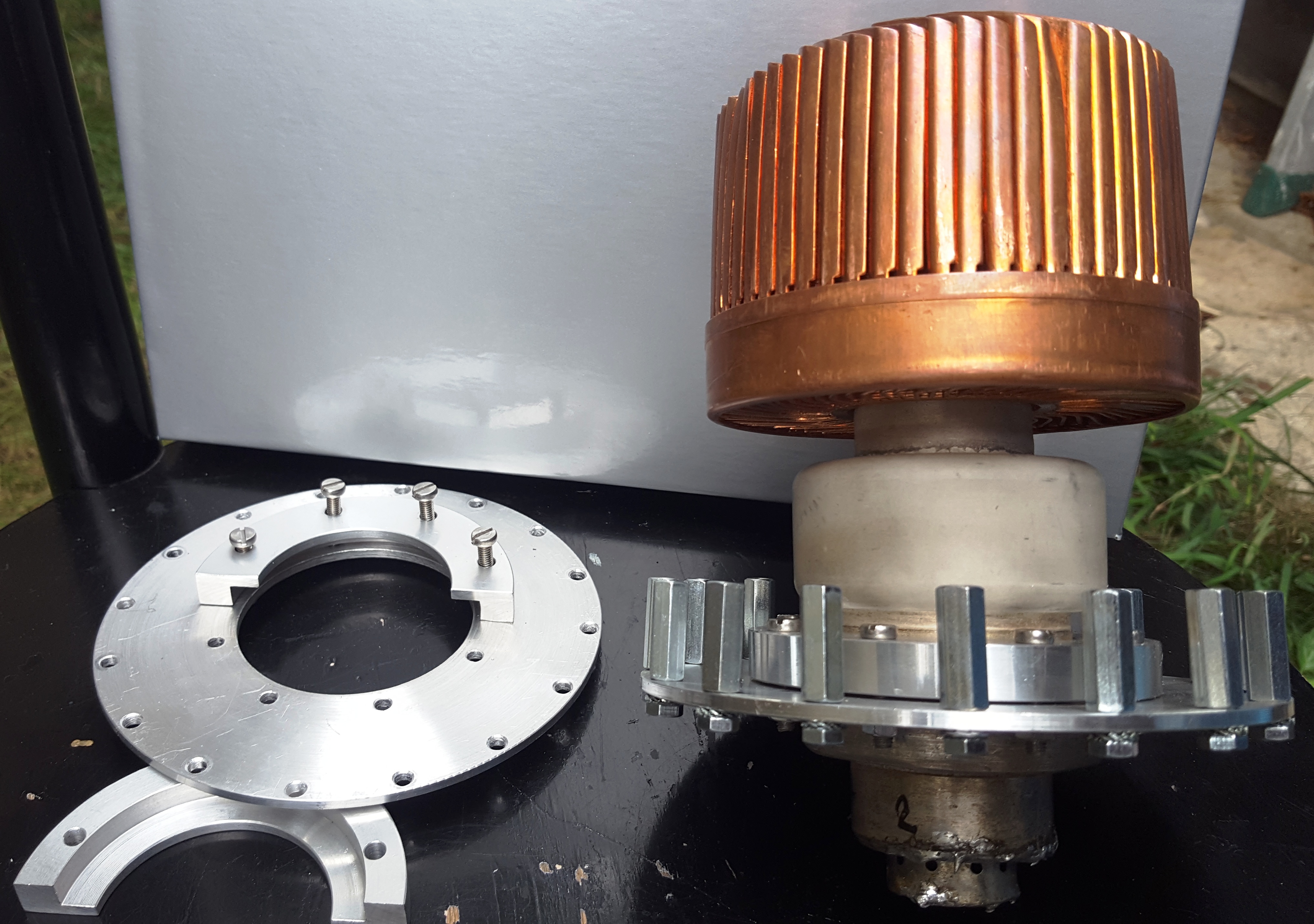
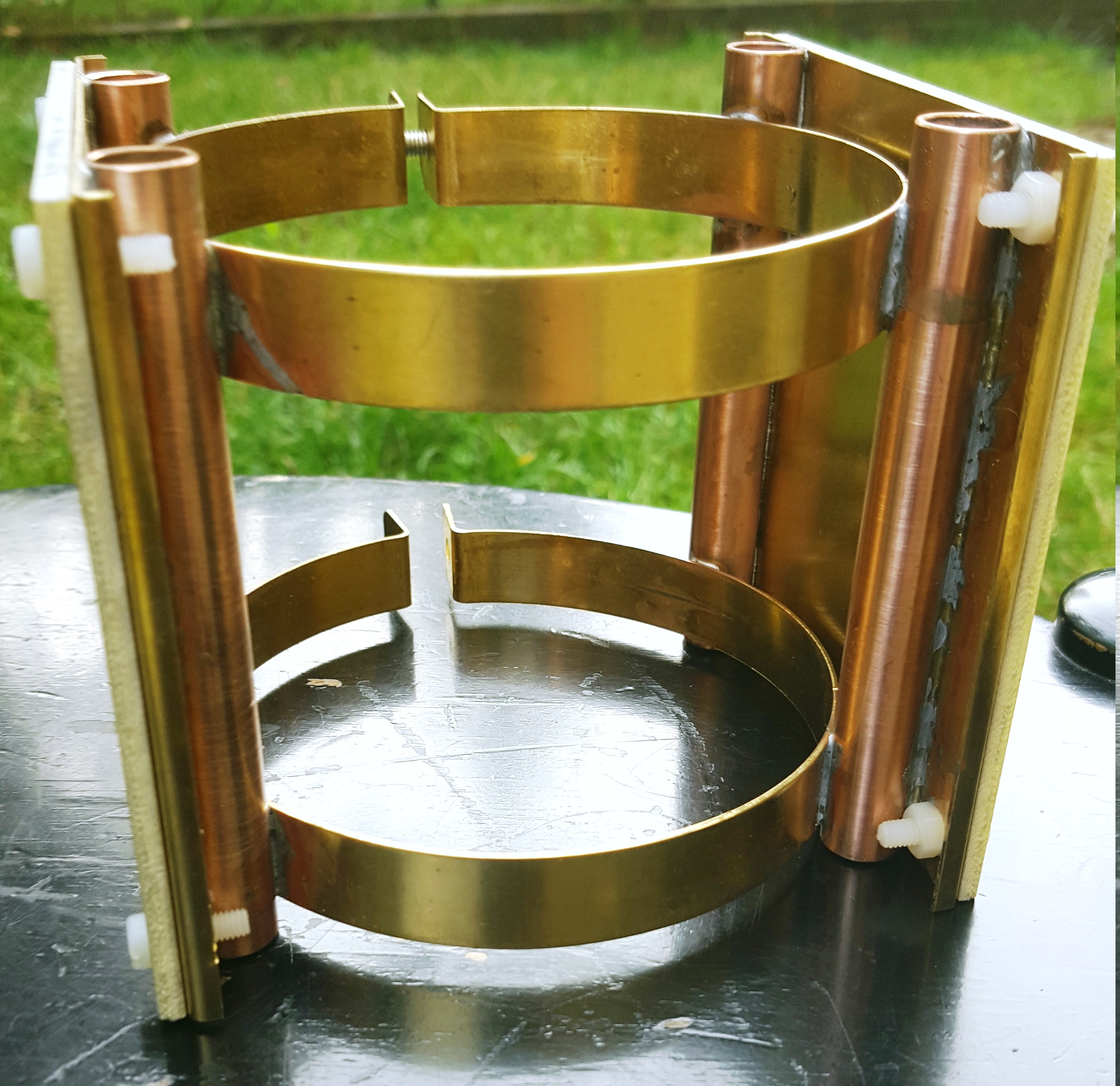
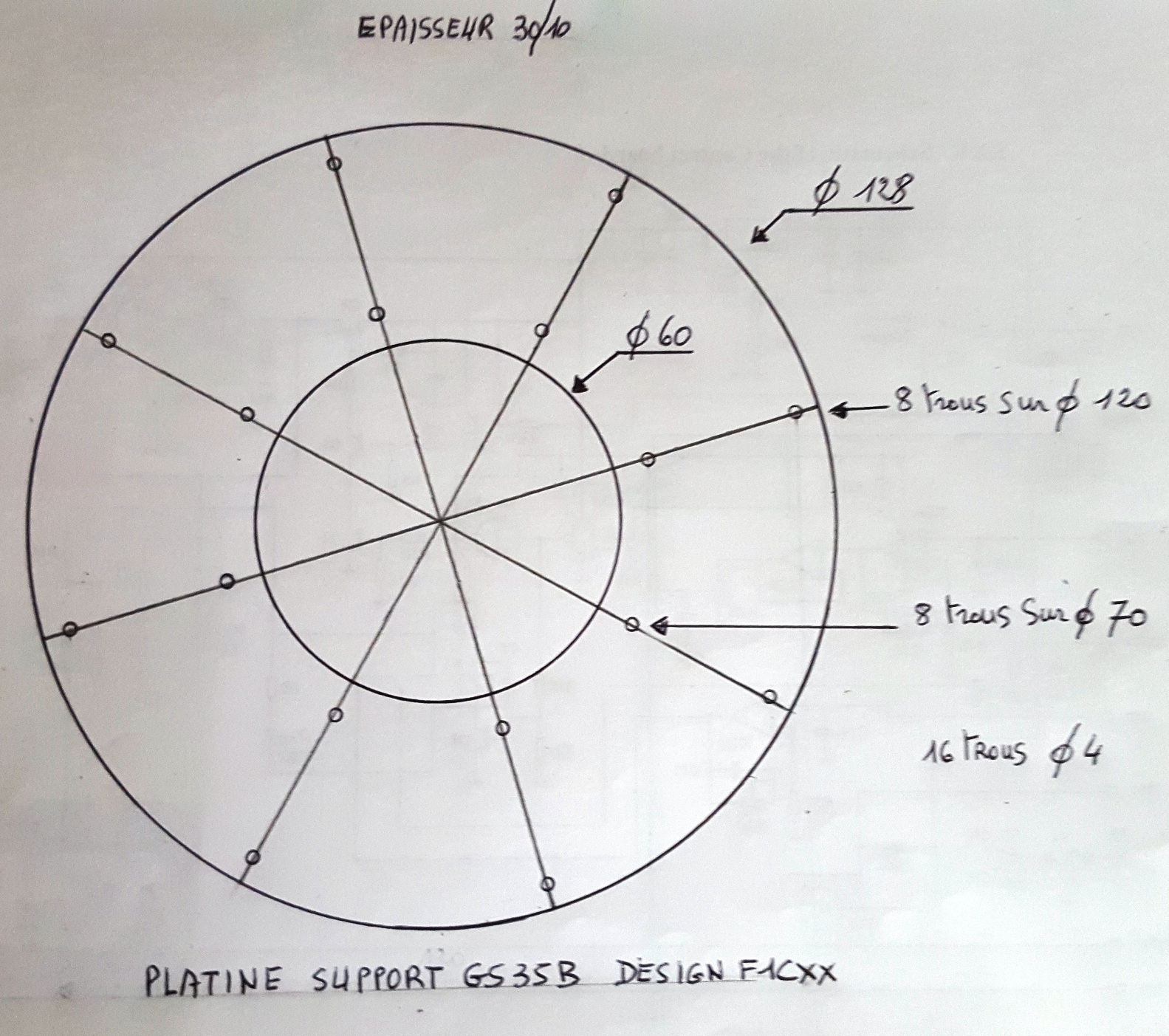
The Socket
I realized this first support in 15/10 In brass sheet metal

It can also be made in 30/10 aluminum sheet. 20mm long spacers are used to fix
the base plate of the bracket to the chassis.
The most complicated will be to make two half-shells in aluminum which will be
used to fix the grid of the tube to the ground.
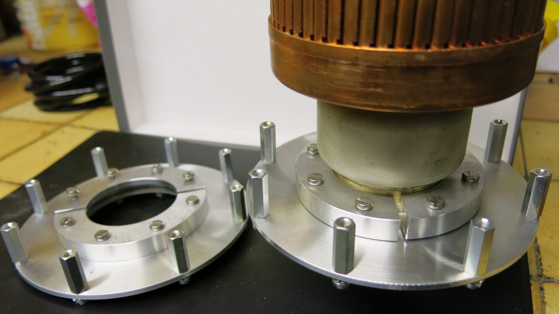
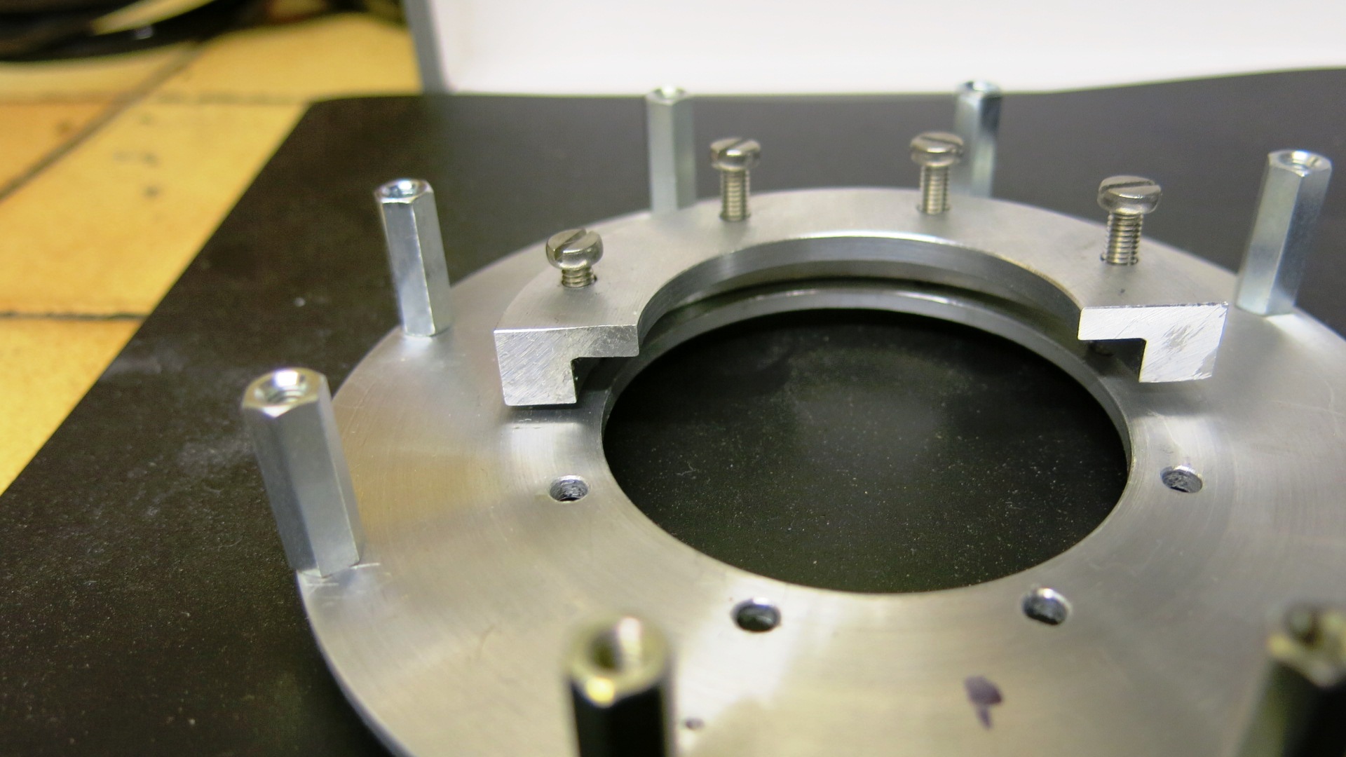
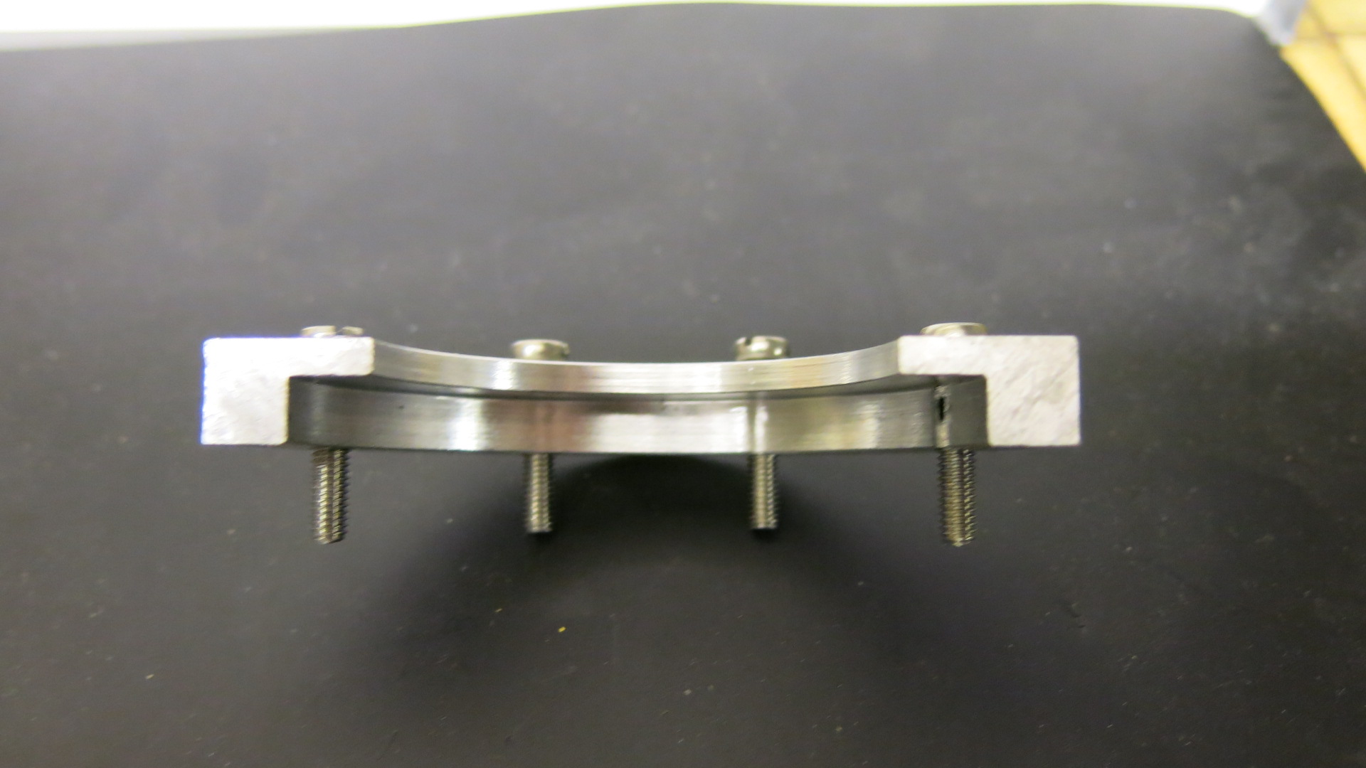
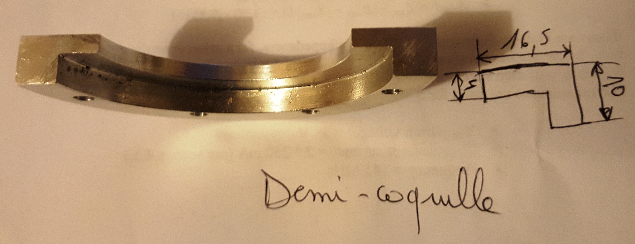
A good ground is essential-For example, fixing the grille to the ground by 4 screws and washers is to be avoided in VHF / UHF.
Important
The turbine must
cool the anode of the tube but also the bottom of the tube / cathode /
filaments.
The turbine will be fixed in the cathode / filament compartment.
The cooling will be carried out either by the total pressurization of the cavity
or by the addition of a chimney between the anode of the tube and the chassis.
In this case the air arriving through the lower box will travel directly through
the fins of the tube and into the line.
Heater circuit
The two heater chokes will be fixed at 90 degrees to avoid coupling between the
two chokes.
They will be wound one in one direction and the other in the opposite direction.
Take 25 turns enameled wire 15/10 on a diameter 8 mm, length about 35mm.
You will gain a few watts !!
I have always regulated filaments. This makes it possible to increase the
longevity of the tube.
Notably when using PA with portable station. To do this a switching power supply
is used
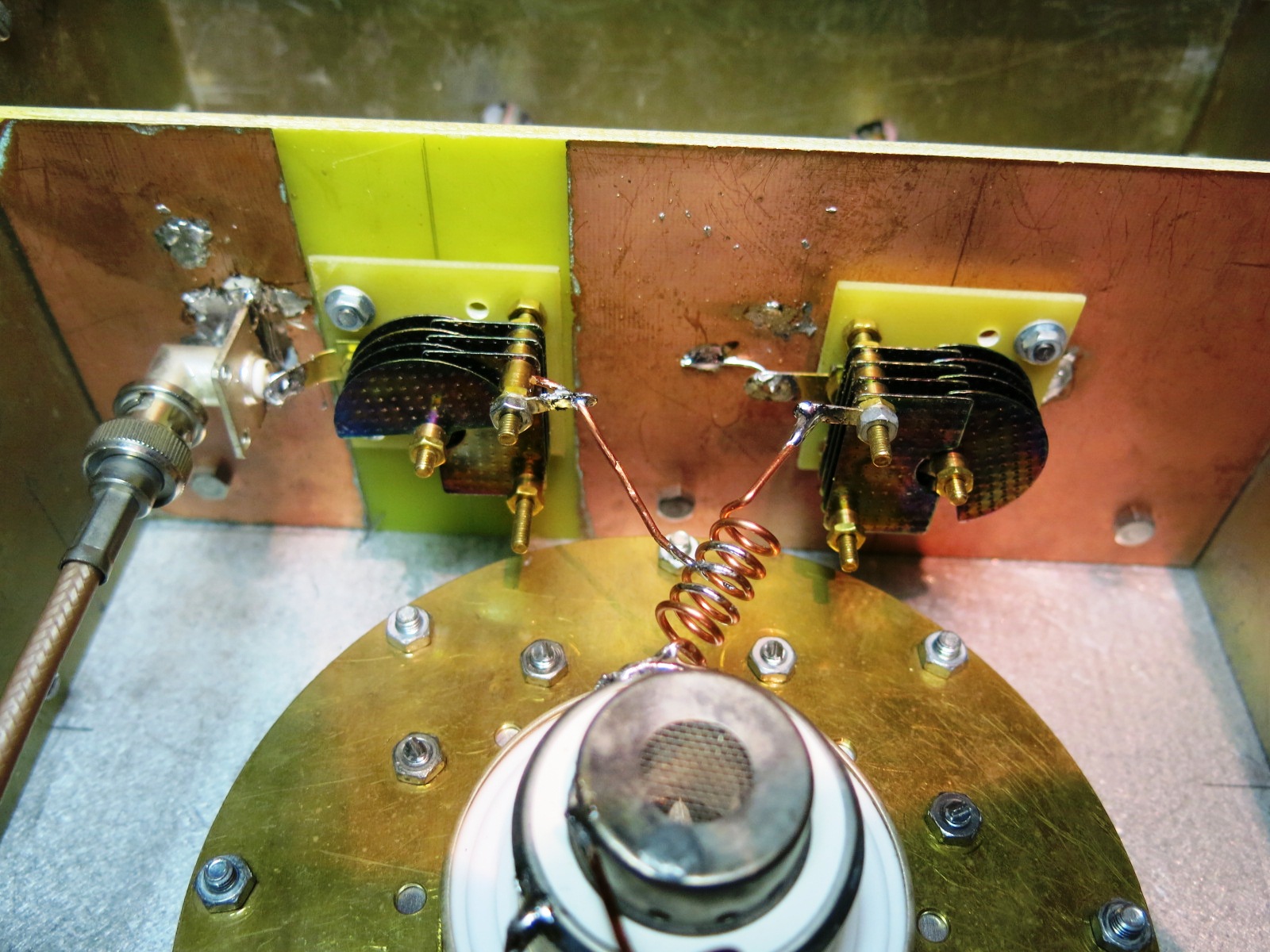
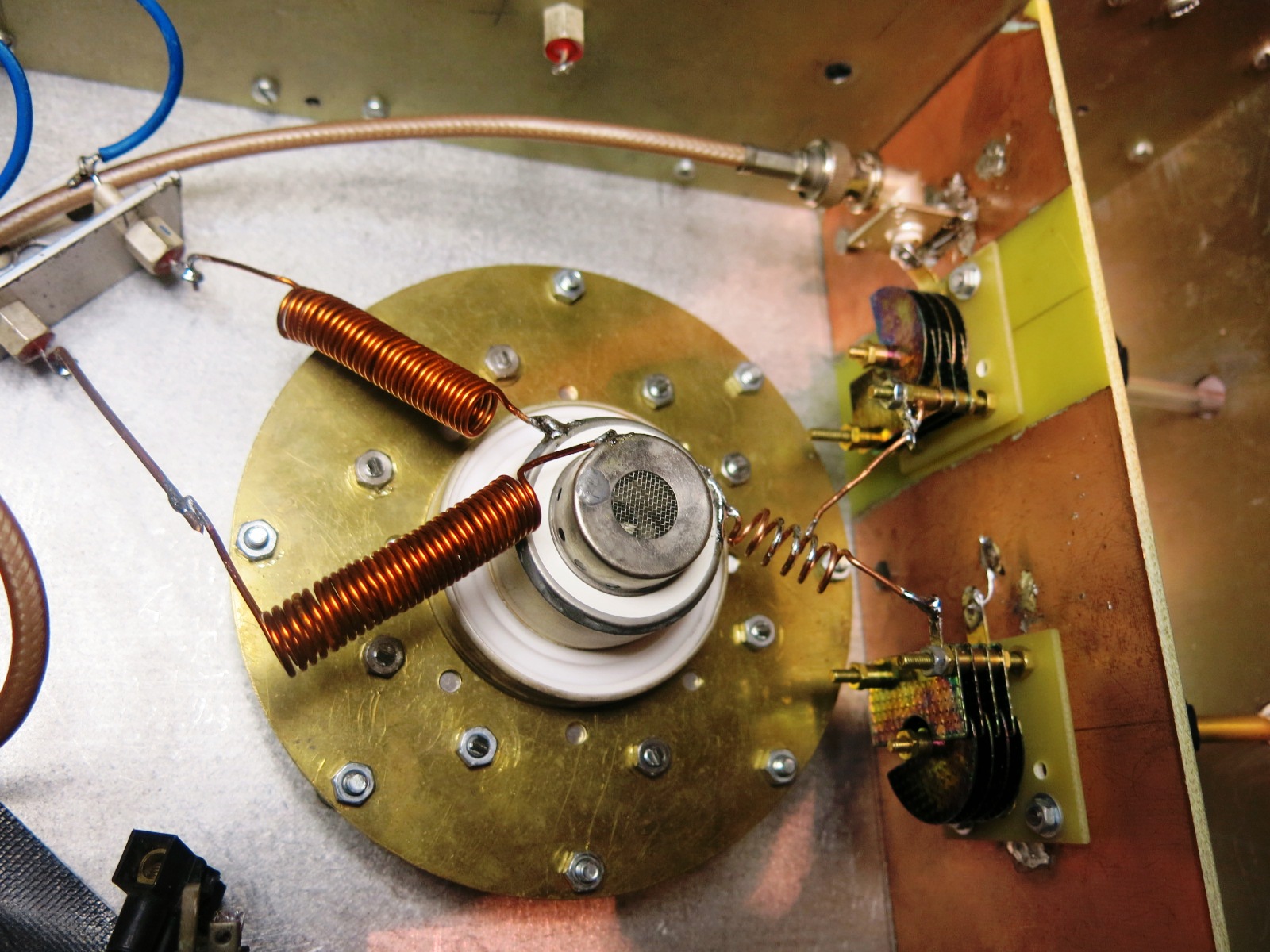
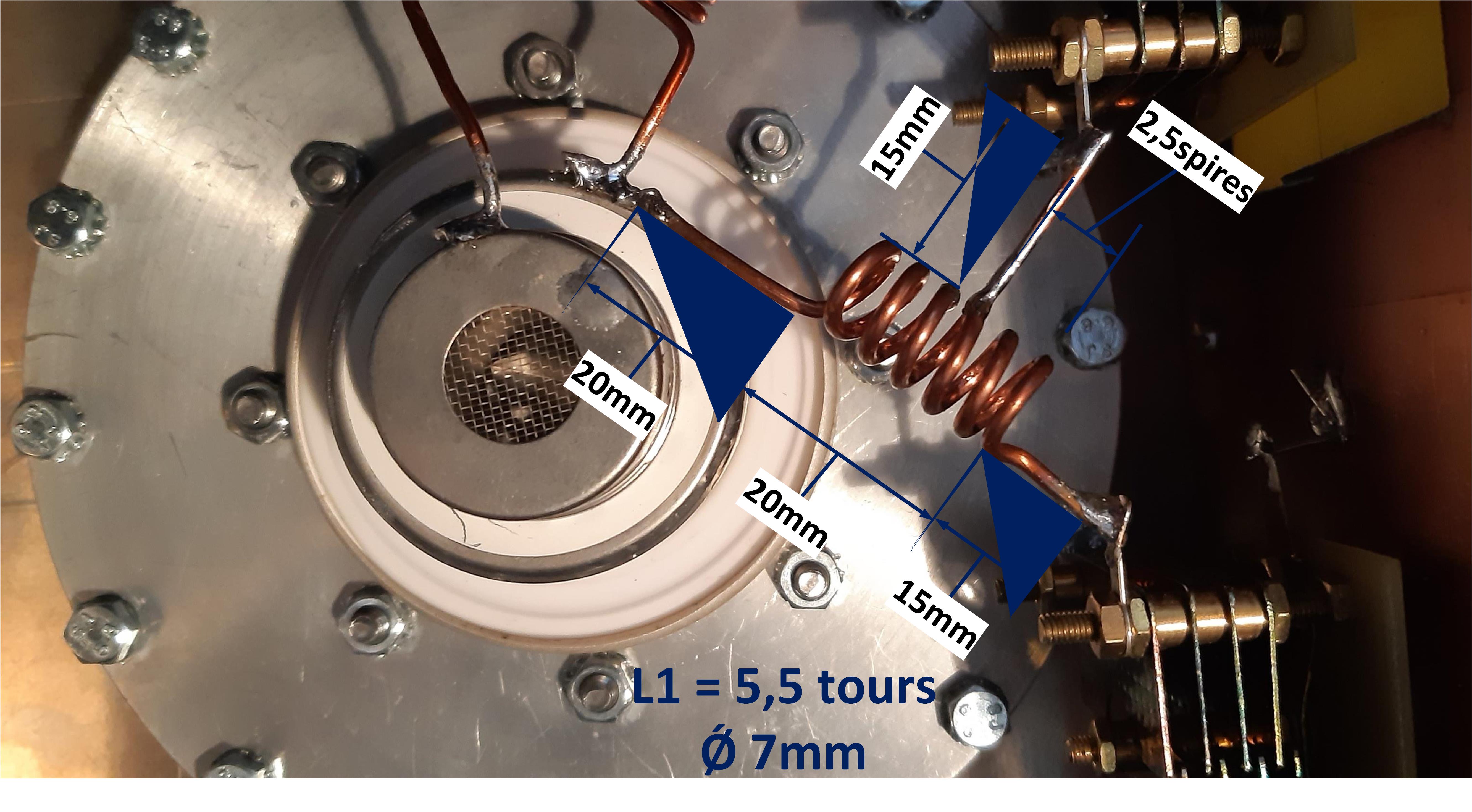
The input circuit
I realized several input circuits that work. A few years ago I opted for the
circuit described by Jean-Pierre F5OAU.
It consists of a choke of 6 turns 15/10 on a diameter of 7 mm. On one side it is
connected to the cathode
and on the other to a CV of about 20 pf which goes to the ground.
The entrance is made by a CV of about 20 Pf which attacks the self to its half
about.
This cv is in series and must be isolated from the mass as well the control rod
of the CV.
Several tests
will be necessary to find the optimum point.
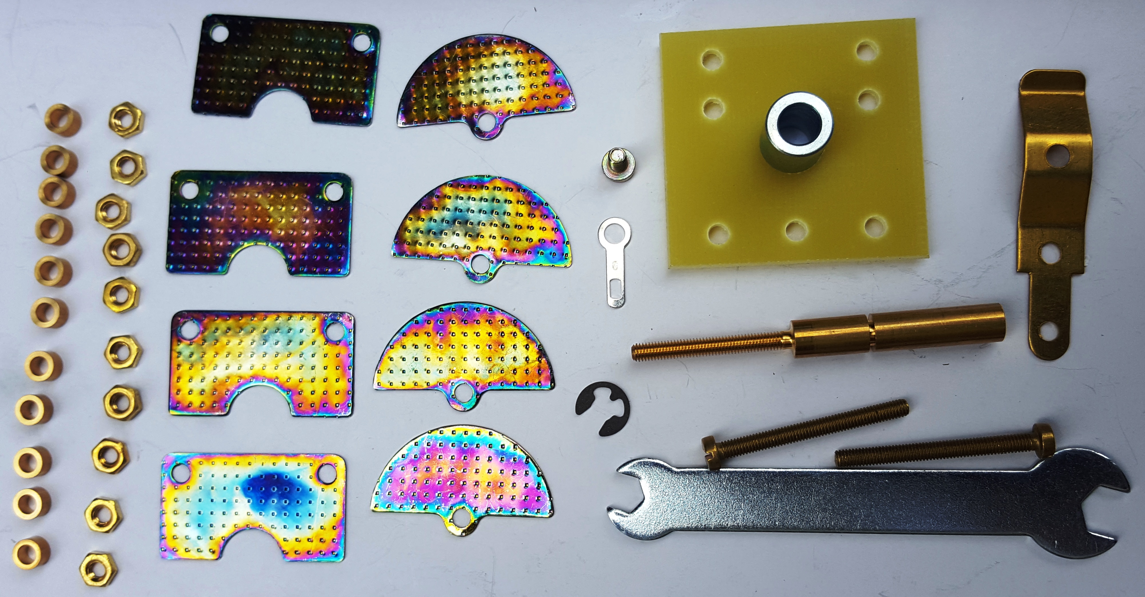
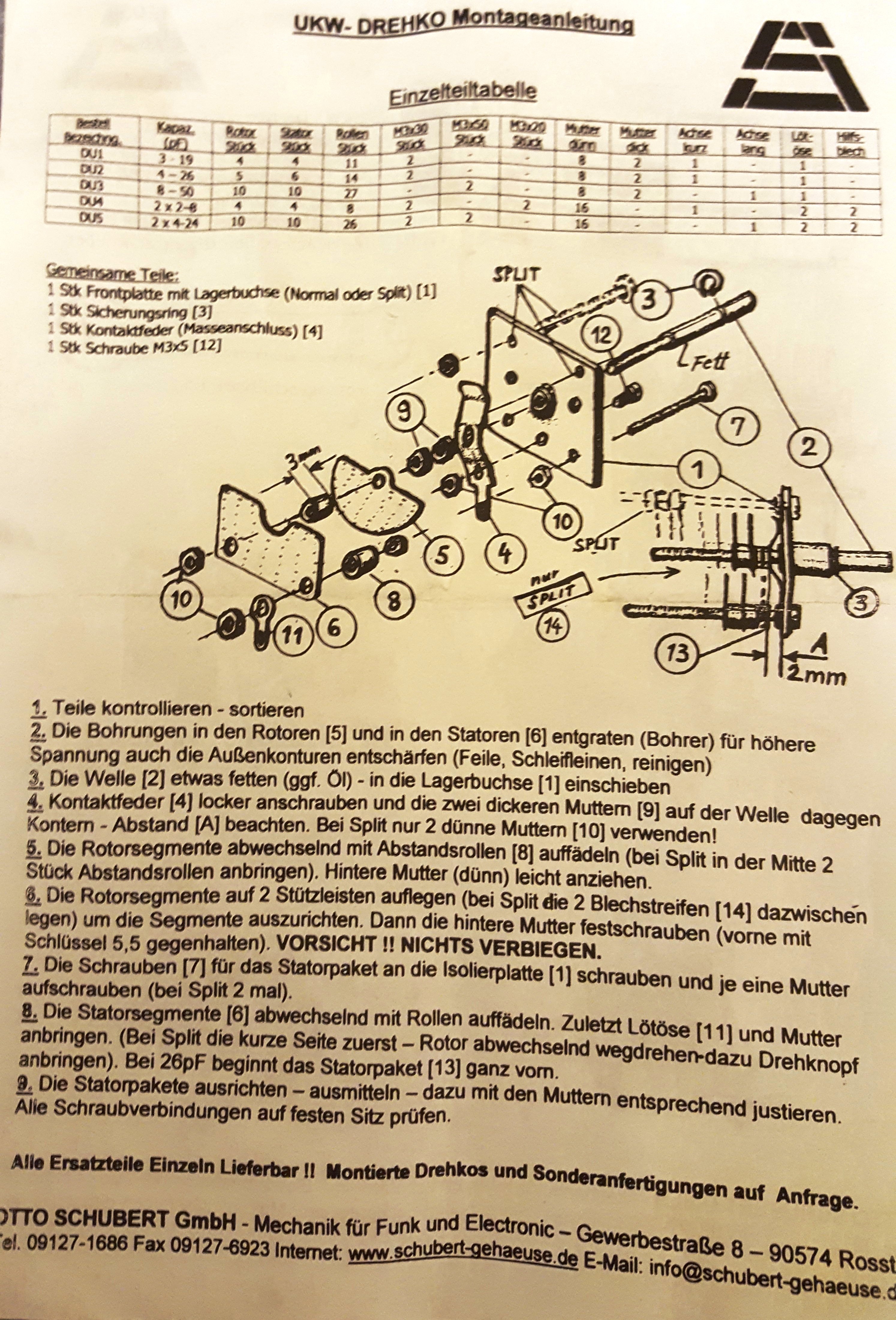
The surplus original CVs have been replaced by CVs manufactured by Otto Schubert
www.schubert-gehaeuse.de
These CVs are modular and allow you to adapt the value necessary for the
assembly. (Stacking of slats modular).
The turbine timing circuit
You will find on EBay, for a few money various circuits of timing ready to use.
To control a power contactor with 220v coil from a 12v relay (k101 / hv
controller on the G3SEK doc)
you can use this small circuit also available on Ebay:
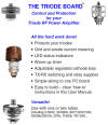
Control card and safety devices
This PA is used with the control and protection card developed by G3SEK "triode board".
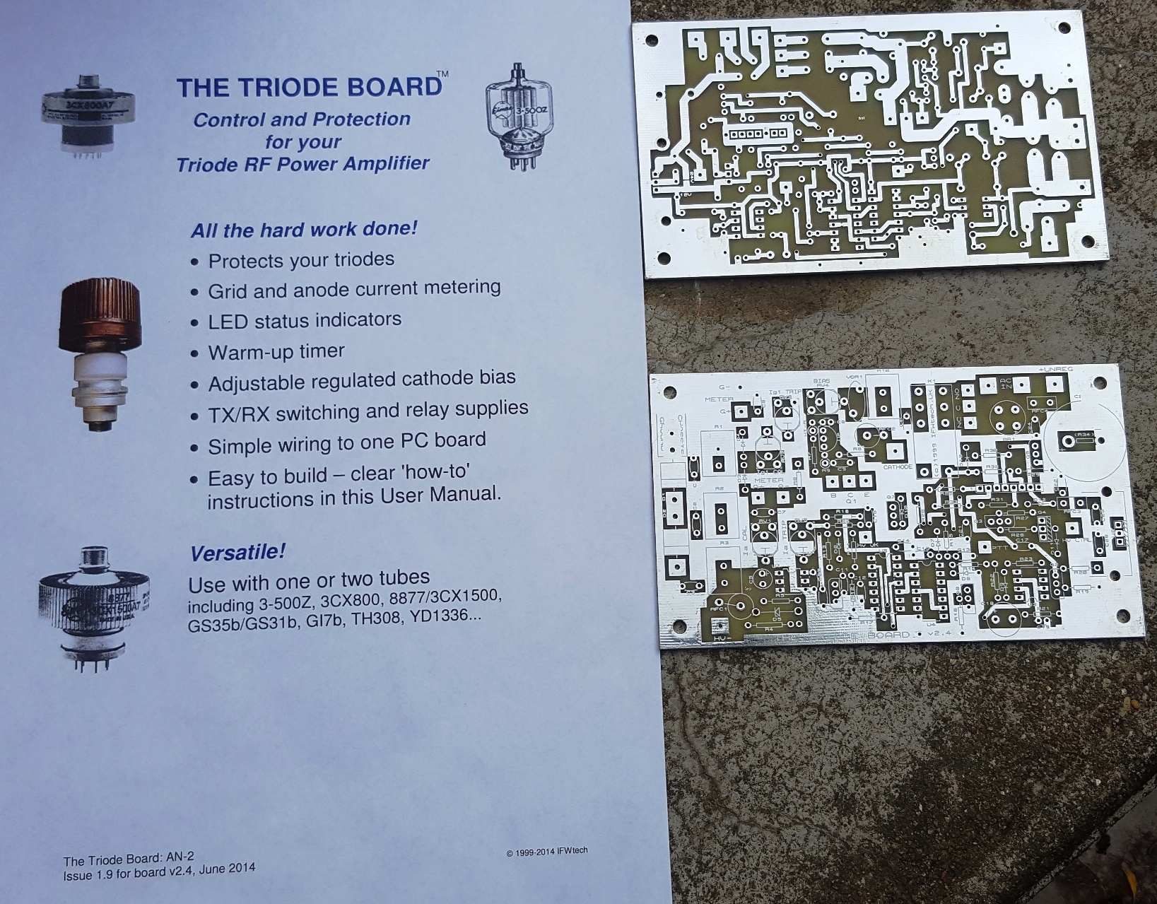
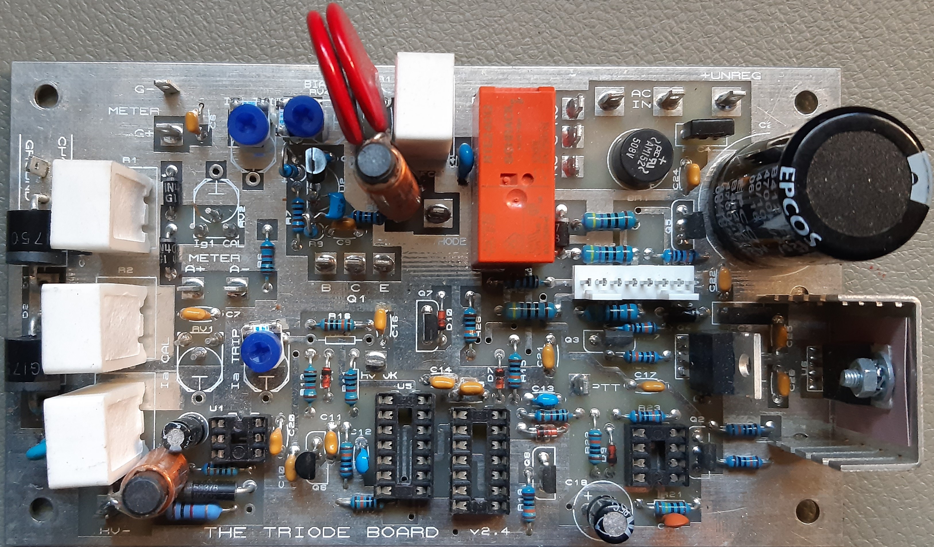
The screen printed card is double-sided and also tinned.
These cards have been sold by thousands and used worldwide.
http://www.ifwtech.co.uk/g3sek/boards/triode/triode-1.htm
You can order
for a very reasonable price at the following address :
http://www.ifwtech.co.uk/g3sek/boards/boardshop.htm#3board
PRECAUTIONS
BEFORE USING TUBES
The tubes used in amplifiers are frequently bought in flea markets.
These tubes from the surplus have often been stored for many months/years and
require a reconditioning before use.
Caution : The use of these tubes without a reconditioning procedure will destroy the tube due to inter-electrode flashes inside the tube.
Several methods exist and are indicated for example on PA0FRI or SM5BSZ websites.
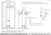
HIGHT VOLTAGE DC POWER

The power supply described above has been designed as simply as possible.
It is designed to work with the G3 / GM3SEK triode board, but can be used for
other systems.
Safety and associated electronics have been kept to a minimum.
The other necessary security features are present on the “triode board” card.
Principle
As soon as the HV power supply is connected to the AC 230V, the L1 indicator lights up indicating the presence of AC voltage.
START-UP
1 / Switch on by switch SW1 on ON
2 / Starting the turbine with the switch SW2 on ON.
Note / the turbine start-up implements SW3 safety.
The safety contact is in series in the switching chain. If it is not closed, CT1
and CT2 are not supplied.
3 / Press the SW4 button for approximately 80 seconds until the green "ready"
LED lights up and then release the button.
This process short-circuits the "hv control" safety contact at start-up.
The 80 seconds are generated by the timing of the “triode board” card.
Note / the TP1 timer (a few seconds) controls the switching on/off of the resistor R1 necessary (at start-up) to supply the HV transformer.
SHUTDOWN
1 / Set the main switch SW1 to OFF.
2 / Let the turbine run for the time necessary for the cooling of the tube (including
cathode / heater).
(At the initiative of the user)
3 / set the turbine switch SW2 to OFF
NOTE / for reasons of simplicity, no turbine on / off delay has been provided.
4 / Disconnect the HV power supply from ac 230v. (Optional)
In conclusion
I designed, realized and tested this Pa in 2003. From 2004 it was used successfully for 144 mhz contests.
To this day,
this Pa gives complete satisfaction. With 4200 volts charging, an idle current
of 150 Ma, Ia current of 0.9 to 1 ampere
with a drive of 110 watts, his output power is 2300 watts, on Bird Dummy-Load.
| U = 4200V Iao = 150 mA | |||||
| INPUT POWER | ANODE CURRENT | GRID CURRENT | OUTPUT POWER | POWER GAIN | EFFICENCY |
| 20W | 450mA | 40mA | 500W | 13,98db | 26% |
| 50W | 550mA | 150mA | 1200W | 13,8db | 52% |
| 90W | 850mA | 290mA | 1900W | 13,2db | 53% |
| 100W | 900mA | 300mA | 2000W | 13db | 53% |
The drive must be limited to the maximum for a moderate use on the air.
Caution
You will find on
some sites other descriptions or copies of my Pa, my socket etc.. with numerous
worksheets and simulations.
If you are seduced by these descriptions so much better but ask to the author
if these descriptions and simulations have been concretized
at least by the construction of a Pa and if it works !! ... If yes. By whom !!
RESPECT SCRUPULOUSLY MY DIMENSIONS INDICATED AND YOU WILL BE INSURED TO EXIT WATTS !! ....
Good realization….
See you soon on the air ...
Thank you to my friend YVES F1BHY for the realization of several mechanical parts
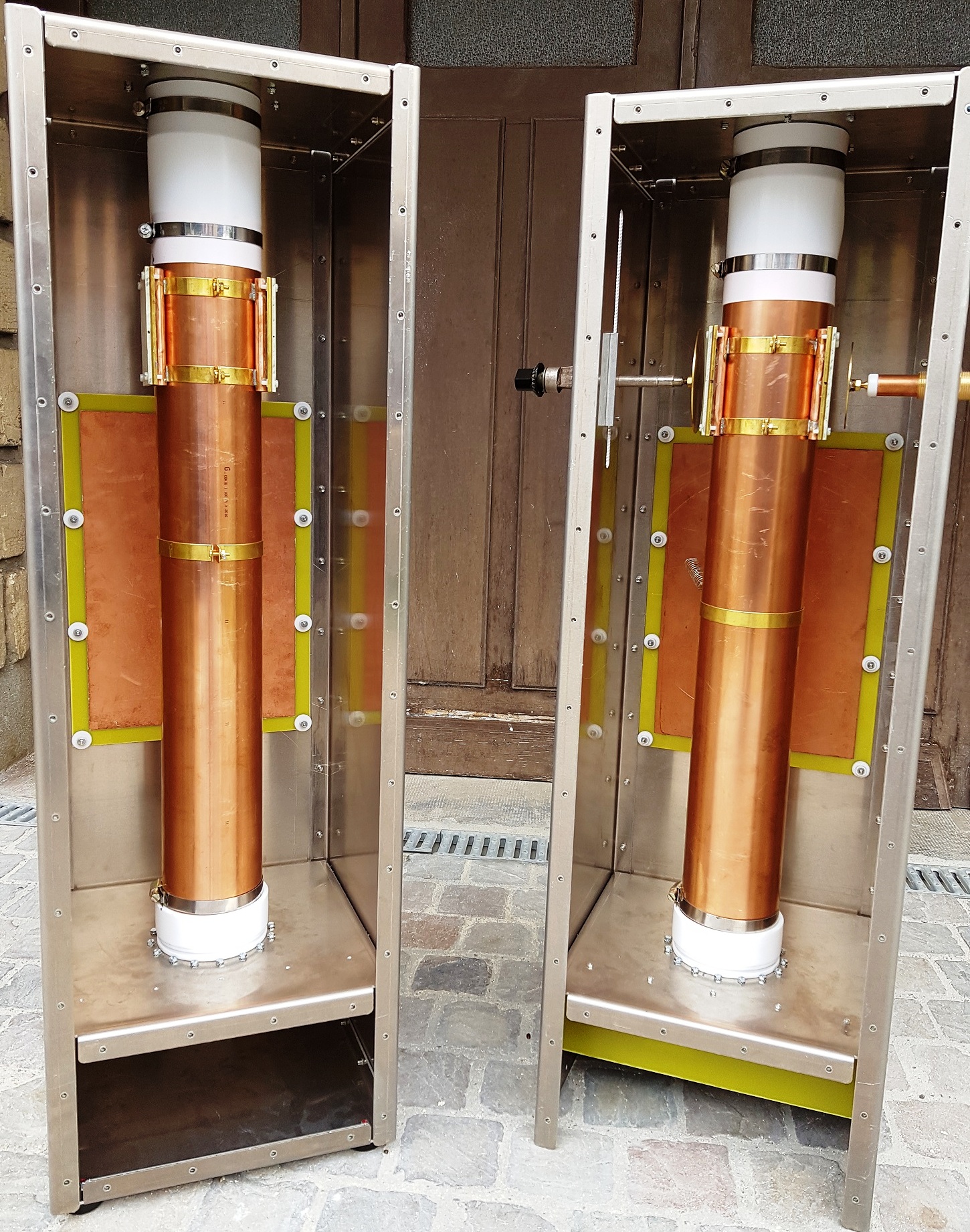
PROJETS
Projects become reality
4 new Pa have been successfully completed..!!!
Several mechanical versions of the cavity are available.
- One box with identical front and rear faces without drilling
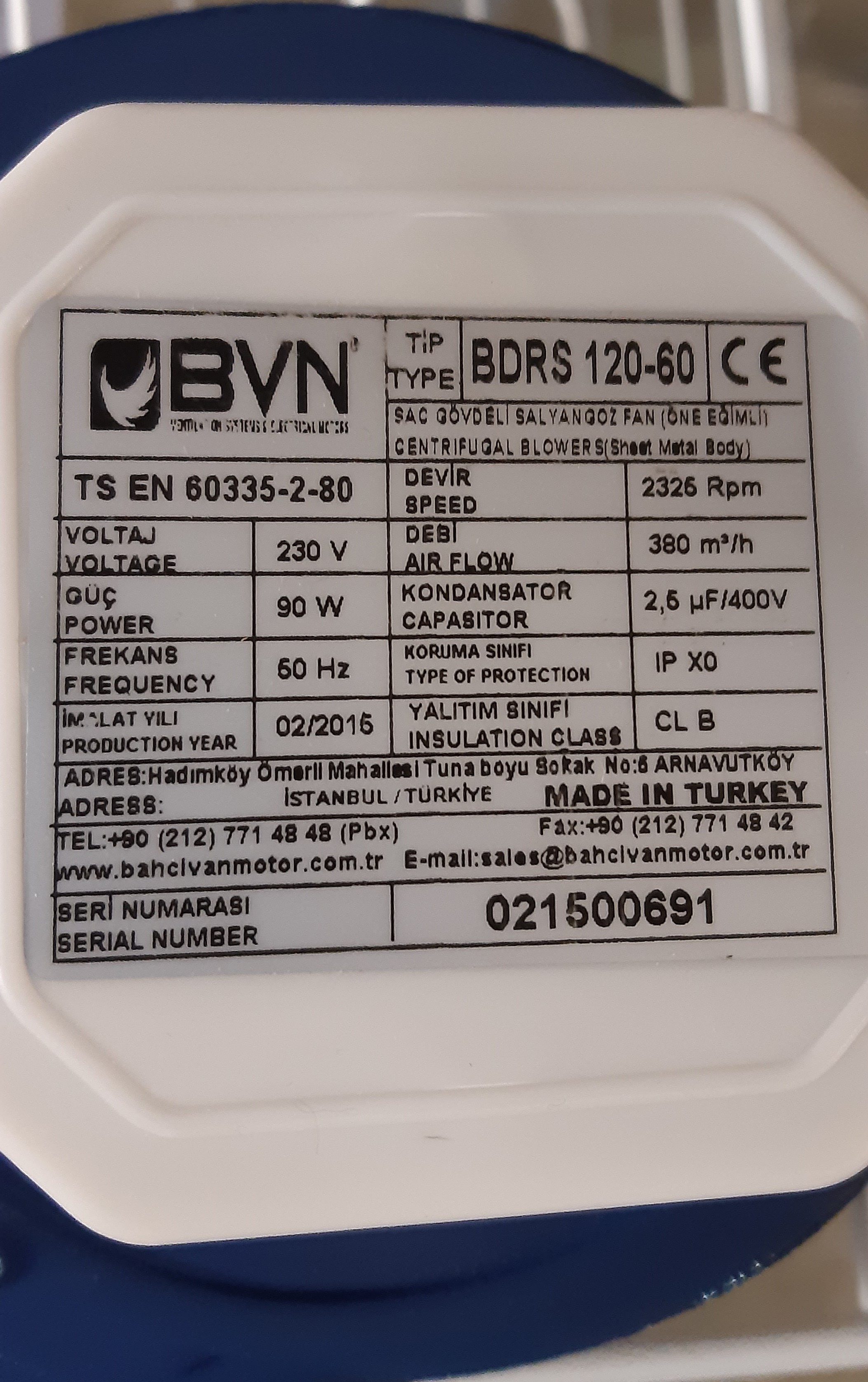
- One box with the rear face comprises drilling dimensions for a turbine ref: BDRS 120-60.
(Any other turbine delivering sufficient air pressure and airflow may be used.)The two one with identical Lateral sides without drilling
- One box Lateral sides have two grooves of different widths to accommodate the « Tune » and « Load » systems.
These grooves allow you to move tuning systems.And well the under, the top and the intermediate (tube socket)
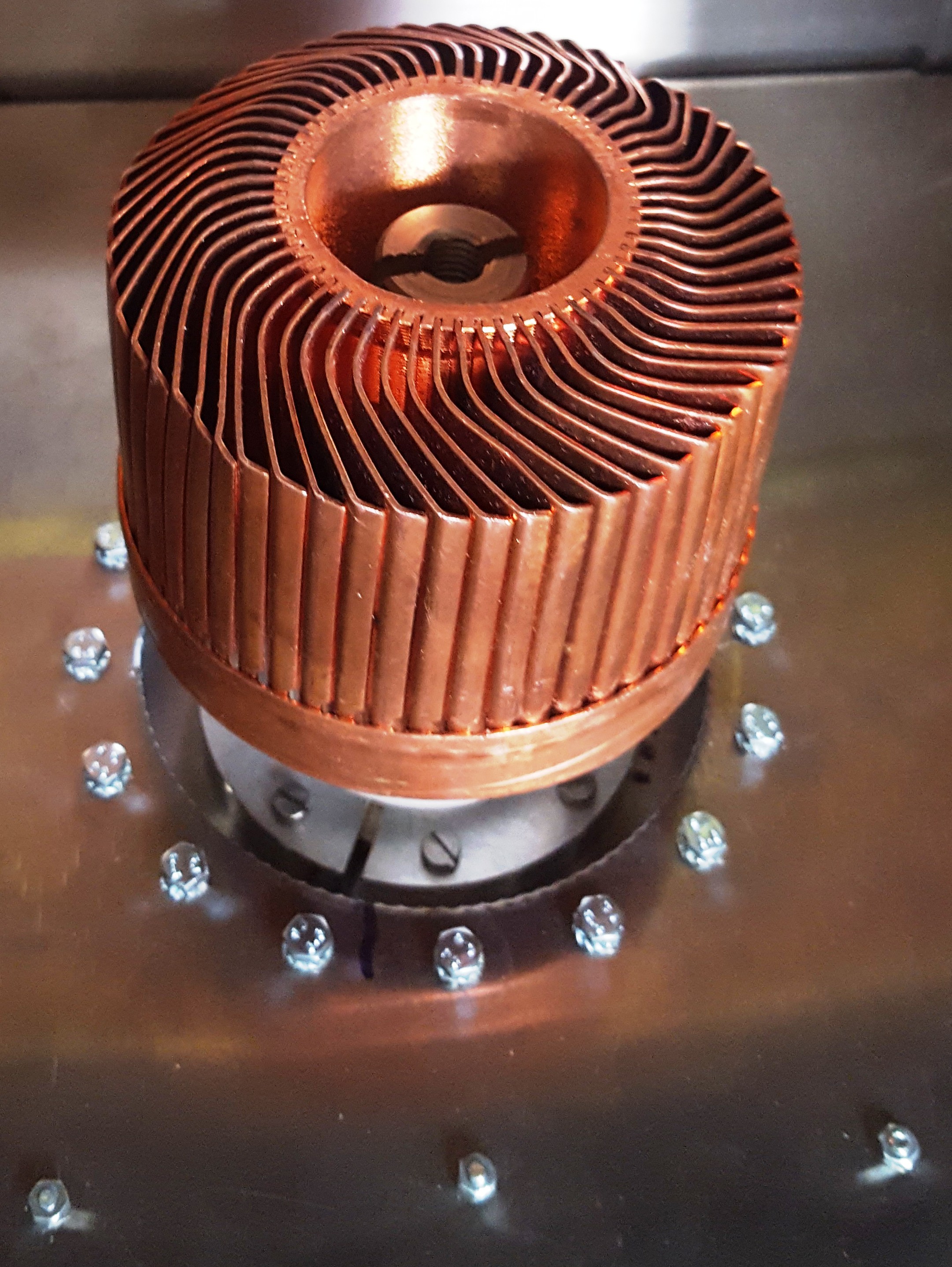
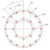
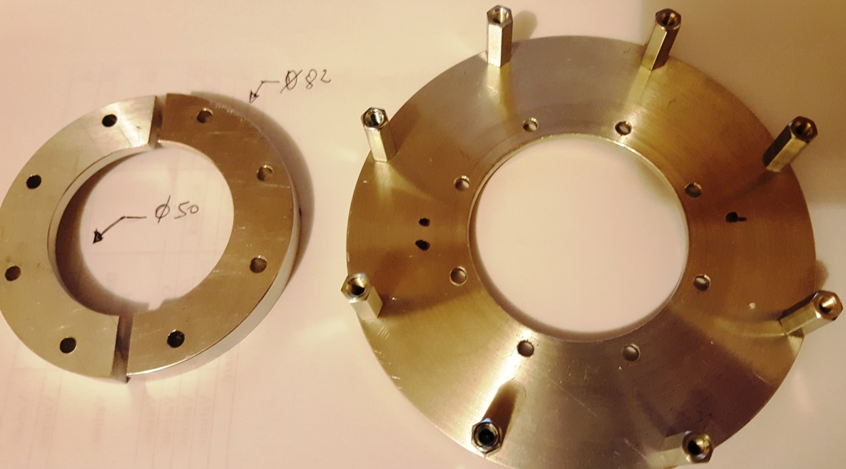
A new Socket is proposed.
It has 16 holes to fix the spacers instead of eight.
The increase in the number of spacers will allow you if necessary to reduce the inductance between tube grid and ground.
A minimum of eight spacers is recommended.
The use of 16 spacers will further reduce the air flow from the turbine.
Note / the first support I have carried out has eight spacers and gives full satisfaction since 2003!
WARNING: THIS SOCKET IS DESIGNED FOR GS31b & GS35b TUBES TO BE USE IN HF/VHF...not in UHF.
Franck, F1CXX (ex J28EL)
OP : TM2K / TM0HQ /
F6KBF
/
F8KGU
|